Product description
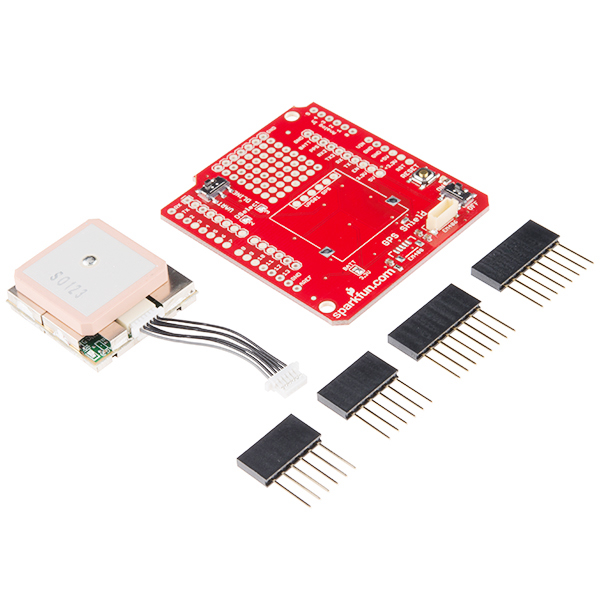
This is the SparkFun GPS Shield Kit, a great launch pad for anyone looking to get into the world of GPS. This little kit includes our GPS Shield, an EM-506 GPS Receiver with interface cable, and a set of R3 headers to solder onto the shield. Adding GPS to your Arduino has never been easier. Multiple GPS receivers attach easily to the shield, and with the example sketch, you will be able to locate your exact position within a few meters. GPS also gives you amazingly accurate time!
A connector for the popular EM-506 GPS receiver is populated on the board, and footprints for EM-408 and EB-85A connectors are also made available (connectors are not included). The regular GPS pins (RX, TX, PPS, etc.) are also broken out to a 10-pin 0.1" pitch header, and a small prototyping area is also provided.
The DLINE/UART switch switches the GPS module's input/output between Arduino's standard TX/RX pins or any digital pins on the Arduino (default setting uses pins 3 and 2 connected to TX and RX, respectively). The DLINE/UART switch must be set to DLINE in order to upload code through the Arduino IDE.
The shield also includes the footprint for a 12mm coin cell battery holder to provide battery backup to the optional EB-85A GPS module.An ON/OFF switch is included which controls power to the GPS module. Additionally, the Arduino reset switch is also brought out.
Includes:
1x GPS Shield
1x EM-506 GPS Module
1x Arduino Stackable Header Kit - R3
Features:
EM-506 connector populated
EM-408 and EB-85A connector footprints provided and connected for optional use
UP501 connector and footprint
Coin cell battery socket footprint provided and connected for optional battery backup of EB-85A GPS module
Standard Arduino sized shield
Prototyping area
GPS serial and PPS signals broken out to a 0.1" header for additional device connections
Arduino reset button
DLINE/UART switch controls serial communications
ON/OFF switch controls power to GPS module